2021-12-20

Nothing happening?

No posts for 12 days! What's going on?

My plan was to get the front and rear panels cut by now but various things have got in the way, not least the fact that it is very cold in my garage and working indoors just seems to be more appealing. However, I have not been entirely idle...

I decided that I would invest in a bench drill (drill press to our American friends) as a prerequisite to drilling the large holes for the fans. While investigating how best to mount it, I decided that the old bench was in need of repair. It was built by my father, some time in the 1960s, using Handy Angle. UK readers of a certain age may well remember Handy Angle, slotted angle about 40mm a side, made from a strong aluminium alloy. The nearest thing to it these days is probably Dexion but I think that is only made in steel. 

Anyway, the wooden work top, which I replaced perhaps 30 years ago was very much on its last legs after a few decades of sawing and drilling and generally bashing bits of metalwork. As luck would have it, I have recently had a new kitchen fitted and the very substantial tall cabinet end panels from the old kitchen cabinets would make an excellent worktop so that became the cunning plan. The panel is almost exactly the right length, 2140mm but at 600mm wide it is about 100mm deeper than the original workbench. 

I thought it would be better to deepen the work bench rather than attempt to cut down the panel, so some more aluminium angle to extend the frame was needed. Of course Handy Angle is no longer available but in this case ordinary 40mm x 40mm x 3mm angle will do the job perfectly well - just drill M6 holes as needed, I ordered the necessary materials cut to length from Aluminium Warehouse a few days ago and they have just arrived as I am writing this missive, so I have work to do! I have a nice new vice (vise) and the aforementioned bench drill ready to go, once I finish the workbench. 

Meanwhile, in the warmth of the shack, I have added a fair amount of new code to the controller and tidied up the wiring somewhat. Having now fixed the problem with correctly measuring heatsink temperature I've also been able to complete the temperature sensor and fan control logic, so the fans only come on to the extent that they are needed.

The control touchscreen layout has also received some attention, with various options such as variable brightness and beep level added to a nascent "settings" page. I expect more stuff to be added to that page in due course. There is now a timer which counts the number of seconds that the amplifier has been in Operate mode (50V supply on) and the number of PTT seconds (actually transmitting). It'll be interesting to see what the ratio is but I am guessing less than 20% TX time in normal use.

Well, I suppose I had better go and brave the Cumbrian chill (3°C as I type this) and get that workbench finished.

2021-12-08

Some practical experience

It was time to get on the air. A convenient UKAC 2m contest was later in the day and first hand experience had shown that 100W really does not cut it from IO84. It nearly didn't happen because of storm Barra, which raced across 'WGV-land at a rate of knots during the afternoon, forcing me to luff my tower over. As the 8pm start time approached thing seemed to be calming down, so I decided to risk raising the tower and give it a try.

Yes, definitely an improvement. Conditions were pretty flat but QSOs were easier to come by and with less waiting around while all the other stronger stations made it ahead of me. A total of 25 QSOs was a bit better than I have managed in the past but importantly almost everyone I called I was able to make a QSO with and I even got a few replies to my CQs that hasn't really happened before.

A few minor problems emerged. The lash-up arrangement meant that RF was getting into places it shouldn't, making monitoring of power output and SWR difficult. I already knew that I would have to write software to perform peak hold/slow decay functions on the various meters and the contest proved that emphatically.

Post contest I have spent some time on the peak hold/decay software and that is now more or less working. I've probably reached the point at which I need to put more effort into the hardware, completing the front and rear panels and getting the amplifier into its case. Why do I always end up doing these projects in mid winter when the garage is more appropriately a place for the car to live in rather than a freezing cold workshop? 

Generally the software is now usable but working on that is a lot more warm and comfortable so no doubt that will continue. I know I have to fix some RF ingress issues and the heatsink temperature monitor is not reading correctly but those are (probably) minor issues.

Drilling big holes for fans is next I think.

2021-12-06

It works!

With the metalwork more or less completed, the PCB to hand and the software coming along nicely it was time to connect it all up and see what happened.

There is some serious electrical energy lurking around in this sort of kit, capable of making big (expensive!) bangs, so I wanted to carefully test out each stage as I went along. First up was checking that the power control logic was working OK, both hardware and software. As is the way with these things that showed up a couple of minor problems, or design mistakes as they are more properly known. A bit of hacking at tracks on the PCB soon fixed the problem that the PSU on/off control was working the wrong way round - on when it was supposed to be off. Note to self - you need the normally open contacts on the relay, not the normally closed ones... eejit! 

More and more components were added to the PCB as more functions were completed. The fan control software and associated circuitry turned out to be more of a challenge than it rightly should have been due to me forgetting which way up PNP transistors go. Once upon a time I understood all this stuff but I suppose I have been a software geek for too long now and I'm getting rusty on some of the electronics basics. Anyway, it's working now.

Eventually the PCB was fully populated and all tests completed. It was time to apply power to the amplifier. Scary stuff... mistakes could be expensive. In fact it was a complete non-event: the 50V and bias LEDs lit up and that was that. The RF side followed, with changeover relays , a 10dB pad on the amplifier input and the various coaxial cables to be connected. 

The amplifier lash-up ready for testing... wires everywhere!


An initial test with 10W output from the IC9700 (1W input to the amp) showed that the amp was producing about 150W output - an excellent result. Unfortunately, and to be expected, RF was now getting places it should not and it was time to apply ferrite rings/sleeves to the sensor lines to stop them jumping about, which seemed to do the trick.

Increasing input power easily pushed the output to our legal maximum of 400W without further incident. That's despite the fact that the amplifier is not in its case and has little of the screening that the completed unit will have. It seems to be a very stable set-up.

It was time to go on the air! Many thanks to Stuart, G4JHV for a useful series of tests, which suggest that all is well and the amplifier is not producing nasty sprogs or unreasonable splatter. Stuart is just 10km away and we had our beams pointing at each other, so this was a very harsh test indeed. Stuart was running low power but was pinning the IC9700 S-meter at the end stop.

So I seem to have a working amp, albeit something of a lash up for now. I plan to give it a more lengthy test in tomorrow evening's 2M UKAC contest and then, if all still seems to be looking good it will be time to complete the metalwork (holes for the fans, etc.), tidy up the internal hardware/wiring and get the amp in its box.

We're not done, of course! There is still a fair bit of software work to do and, as my software projects never really finish, that will be something of an ongoing challenge. I also need to calibrate the power output and SWR indications and to do that properly I shall need to find a suitable calibrated power meter. 

All in all a good day!

2021-12-01

Progress!

Front view
At last the metalwork has arrived, as have the PCBs which came from Hong Kong in less time that the metalwork took to get here from just down the road. Can't help but think that there's a message in there about attitudes to service.

A few other less critical odds and ends have also turned up, so it's time to get down to work. 

Laying out the major components and screening metalwork was first on the agenda.This is where you find out whether it'll all fit and can be made tidy/easy to work on. So far so good - I would not want the enclosure to be any smaller though.

Rear view
Although I had the exact dimensions of the PCB, having it actually to hand made it much easier to visualise how it would fit in. It sits on stand-
offs over the top of a small 12V SMPSU, which will be on at all times unless the rear mains switch on the IEC connector is turned off. Its quiescent power consumption is under 1W so I think I can afford for it to stay on 24x7.

The amplifier section is completely shielded from neighbouring components, including a detachable lid. All coaxial cabling, the changeover relays and cooling fans are all fully contained in this section. 50VDC and the various control/sensor connections are all via 1000pF feed-through capacitors. This should keep the RF where it's meant to be but it will also help with the amplifier cooling by creating an effective wind tunnel front to back.

Amplifier screening lid in place
I still have to cut the front and rear panels. The front panel is just a pair of 100mm diameter holes for the amplifier and PSU fans to pull in air. 

The rear panel also has the two 100mm diameter holes but in addition there will be various connectors: Transceiver in/antenna out coaxials, mains power, PTT input, remote control head output and a micro-USB socket. 

Now that the major components are all fixed in place it will be straightforward to position these items, then another metal bashing session in the garage beckons. Not just yet though... it's pretty cold out there and I am going to warm up doing some inside work for now.

Right, enough of this bloggery... where's my soldering iron?

2021-11-25

PCBs and fans

Annoyingly the metalwork that I need to move the mechanical side of the project on has still not arrived and there appears to be no indication when it will, which is frustrating! I suppose they'll blame the delays on Covid - that seems to be the go-to excuse for poor service everywhere these days. Fortunately I can get on with software and PCB design, although that too will soon run out of steam with no hardware platform on which to test. 

Meanwhile, I have been ruminating on the 50V current monitor design. The issue is that the zero current output from the sensor is Vcc/2 or about 2.5V and at 100mV/Amp sensitivity there was insufficient headroom for a 20A range before the 3.3V limit on the Teensy SBC is reached. I contemplated level shifters, potential dividers and so on but all had significant disadvantages.

Suddenly I had a Eureka moment! I will never have negative current, so why not run the sensor in reverse, so positive current flow results in negative-going sensor output? That way 0A is about 2.5V and 20A is about 0.5V - a range that is entirely within the Teensy's capabilities. A couple of lash-up tests followed and correct operation was observed. Phew! A much better solution. And simpler too. Fewer components on the now redesigned PCB and simpler computing in the software. A win-win situation indeed.

With that change completed I've decided to put PCB Mk1 into production. It'll take about a week for the finished boards to arrive and by then, who knows, I might have the metalwork!

I mentioned a few posts back that the fan in the 50V PSU is rather loud. I decided to investigate with a view to a quiet life. It's easy to get the fan out - just four screws but then things started getting complicated. Looking up the fan model number I found that it is indeed noisy, 40dB(A) no less and that it has a "locked rotor" output, which is active if the fan is not rotating. Easy, thought I, just disable the locked rotor input to fool the PSU into believing all is well, then replace the fan with something quieter.

No PSU output! After much head scratching, I finally realised that the PSU also monitors fan current and once I arranged that the PSU ran happily enough. Research indicates that the old fan produces an impressive 1.3m3/min air flow, which probably explains the noise level. 

As the PSU will never be run even close to flat out and at a very low duty cycle, even in contests, I feel comfortable de-rating that somewhat and have found a suitable looking fan that provides 1.0m3/min at just 24dB(A) - that's 16dB quieter! The fan is on order from RS and should be here tomorrow.

With that I have rather run out of things to do until some more stuff arrives. It's CQWW this weekend and that's always good fun, provided, that is, the forecast 70kt winds don't come to pass. Anything close to that and my tower will definitely be luffed over!

2021-11-23

Coding!

Unfortunately the metalwork has still not arrived due to a shipping error by the supplier and that has left me with nothing other to do than start writing code. Very often initial coding attempts reveal problems in the hardware design and so it proves to be in this case. It is basically an iterative affair.

One such case is the current sensor. The standard device for this job is the ACS712 hall effect sensor which comes in various ratings - for this purpose I have selected the 20A version. It runs off a 5V Vcc supply and, rather annoyingly for this sort of application, is designed to measure current flows in either direction. It does this by setting the output at a nominal Vcc/2 for 0A. positive excursions from this baseline are current flow in one direction, negative excursions the opposite direction. 

1A of current flow is represented by 100mV change in output. 20A, which is the absolute maximum the amplifier should ever take, 16A or so being more commonplace, therefore represents a 2V excursion or (Vcc/2) + 2 = 4.5V. This is a problem, because the Teensy is a 3.3V device.

The simplest solution is a 5:3.3 potential divider, which can be realised with a 4k7 and a 9k1 resistor. This reduces the 0A voltage to 1.67V and 3.3V represents 24.44A at a conversion ratio of 1A = 66.7mV. Although the 3.3V maximum input should never be exceeded in normal operation it makes sense to protect it with a 3V3 zener diode.

Similar considerations apply to the 50V monitor which is fed via a 20:1 potential divider and again the input to the Teensy is protected with a 3V3 zener diode. At full power the VSWR outputs from the amplifier can reach around 5.5V so here a 2:1 potential divider is implemented.

Next I turned my attention to the fan control logic. The Teensy doesn't have any analogue output pins, instead using pulse width modulation (PWM) to vary the average output voltage. All well and good but fans don't much care for 3 kHz square wave power supplies, so some fairly aggressive smoothing is required. Fortunately this is easily achieved once you know that you need to do it. a 47uF electrolytic on the base of the driver transistor works well with the series resistor to reduce the ripple to about 100mV. The fans are now much happier!

All of this has resulted in significant change to the circuitry and, of course, the resulting PCB layout. I think I am getting close to the finished design and it may be time to think about getting the first PCBs produced. I can hold off for another week or two because hopefully some time soon the metalwork will turn up and I can get on with that aspect of the project.

I've also put some effort into screen layout design for the control head. This is as much art as it is engineering, in that we want the finished article to look professional and pleasing to the eye, while also being functional, with good ergonomics. Inevitably there will be multiple iterations but, of course, this is just software, so it is easily changed, unlike committing to a circuit and having the PCB produced. 

Anyway the image shows where I am at in my thought processes so far. This is the main "operating" screen. There is a startup screen and a maintenance screen with diagnostic information... yet to be designed.


2021-11-16

More controller musings

While I wait for components and metalwork to arrive I have been turning some of my earlier ideas for the controller into practical ideas for implementation. I've also written some basic code to test out a few ideas. This has led me to an initial proposal for the controller circuit and PCB layout for same. 

I've settled on an Arduino Teensy 4.0 as the processor. The power supply arrived and I've been experimenting with controlling that. The 240V AC inrush current at switch on is awesome. Fortunately there is a control feature that permits the PSU to be put into standby mode, with the fan stopped and negligible power consumption. I therefore see three distinct power modes:

  1. Off - no power to the 50V PSU, only a small 5V PSU powered up to keep the controller alive, albeit sleeping
  2. Standby - Power applied to 50V PSU but PSU in standby mode
  3. Operate - PSU on, producing 50V

And then, of course, two operating modes:

  1. Receive - amplifier biassed off, amplifier in bypass mode
  2. Transmit - RF to amplifier, lots more RF to antenna!


The 240VAC power switching will, most likely, be via a suitably chunky relay. I might investigate solid state relays for this task. Similarly, using a small, low cost reed relay for the PSU control switching makes isolation of the PSU from the control logic very straightforward.

I've decided to have large, relatively low speed fans front and rear of the amplifier module. The logic in this is noise reduction although unfortunately the PSU fan is far from quiet and is not temperature controlled, so my quiet shack plans might be in vain! I've included circuitry to monitor amplifier heatsink temperature and vary the fan speeds as needed.

Other circuitry includes forward/reflected VSWR acquisition and 50V voltage/current monitoring. There are further processor inputs for PTT and outputs for the change over relays, amplifier bias and, of course, the remote control head. 

Using KiCad I've produced a PCB layout that will easily fit in the available space. The board is 65mm wide and 160mm long and it will sit horizontally to the right of the PSU. It's so cheap and easy to get PCBs made these days that it will probably not be too long before I get the first prototype into production.

Meanwhile, I have written some initial code for the Teensy 4.0 SBC. My plan is to get enough if it working to be able to try out the amplifier, lash-up style in the 2m UKAC on 7th December.


2021-11-13

Control systems - initial musings

I always enjoy projects that involve a mix of hardware and software development and this project provides a nice opportunity to scratch that itch. 

At a basic level it is fairly trivial to control the amplifier. All that's really needed is a transistor or two to take the PTT input from the transceiver and drive the two coaxial relays (transceiver input and amplifier output). The transceiver can deal with delaying the onset of RF for the time taken for the relays to change state (around 20ms).

But that would be boring! There are sensors to monitor:

  • Forward power
  • Reverse power
  • Heat sink temperature
  • 50V supply voltage
  • 50V supply current
  • Fan actual RPM

...and things to exercise control over:

  • Fan required RPM 
  • Amplifier status: off/standby/Tx
  • Amplifier bias
  • Error conditions such as high VSWR, over voltage/current/temperature, etc.

All this points me in the direction of a microprocessor controller. Most likely this will be Arduino-based, probably using a Teensy 4.0 SBC because it is more than capable of handling all the I/O, is small and inexpensive. Eventually I will design a PCB to mount it and all the supporting electronics on to but initially breadboarding will suffice.

Once we have a microprocessor controller it becomes relatively easy to implement a separate control head and that is a good thing because the operating position chez 'WGV is cluttered enough already without adding a 19 inch rack's worth of additional hardware within arm's reach. I am envisaging a remote control head with a single TFT touchscreen display, powered directly from the amplifier. We can use RS232 for this, so only four control wires are needed: Ground, Tx, Rx and +5V. The touchscreen removes the need for any physical switches, so the control head will simply be a small 3.5" screen that can go anywhere in the shack.

I've used Nextion displays for this sort of thing in the past and with their built in processor and RS232 interface I think they will be perfect in this application as well. I am not yet ready to start coding but ideas are forming in my mind and I won't be able to resist making a start soon!

2021-11-11

A box to put it all in

I always like to try to make a nice job of the aesthetics on my home-brew projects. Not for me the old battered aluminium box with holes in the wrong places from earlier projects. It seems to me that if I am spending several hundred pounds on the innards then it is not doing the project justice to then scrimp on the case.

To determine the best sort of case assembly I first looked at the largest components it will have to house. The amplifier module is 250mm (L) x 125mm (W) x 100mm(H) and the power supply is much the same size, though not quite so tall. Between them these two units dictate the size of cabinet. 

A 3U 19 inch rack unit is 425mm (W) x 127mm (H) and comes in various depths - the standard depth closest to the project requirements is 335mm (D). RS Components do a nice range of self contained 19" rack cases and in the end I selected an RS PRO unit, stock number 188-1319.

The amplifier module and the PSU will go side by side, leaving about 70mm of width for ancillary stuff such as control circuitry, processor, etc. Whilst the case will be fairly full, it won't be difficult to work on and its shape makes for a neat logical layout.

Both the amplifier module and the PSU require forced air cooling, so there will be axial fans front and rear, making for some quite large holes to be cut in the two panels. It is notoriously hard to make a good job of these by hand but I shall have a go and if it turns out to be unsatisfactory then I have option B up my sleeve - getting CAD-CAM designed panels made up to my specification. Not cheap, so hopefully it won't come to that. We shall see.

Internally I will mount everything on a removable base plate and fit screens between the amplifier module and the rest of the case. This is partly just good RF engineering practice and partly to help create an effective airflow over the amplifier module's heat sink and components. More on this later.

Externally, I am planning to have no panel controls, opting instead to have a separate control head, so the amplifier can be away from the operating position. There should be nothing on the front panel and just mains power input, RF input & output, PTT in and external control head connections on the rear panel. I've little doubt that there will be much more to say about this in due course.


50V @ 20A!

These days, with switched mode power supplies (SMPS) so commonplace it doesn't make much sense to build a 1kW linear PSU, which would be huge and weigh a ton - quite apart from being very inefficient. I soon discovered that 1kW SMPS are almost as expensive as the RF amplifier module but it turns out that they come up for sale second-hand occasionally at more palatable prices, so off to eBay we go...

In fact I ended up getting the rather more beefy 1500W PSU because there happened to be one for sale at a sensible price. This beast is capable of producing 50V at up to 30A, so I won't be short of oomph! Just look at those 50V output terminals - this power supply means business.

A slight downside of the larger PSU is that it is physically bigger but only in height and that makes little difference to the layout - it's about the same size as the RF module and the two units can conveniently sit side by side. Between them these units largely determine the shape and size of the enclosure, which I will discuss in another post but suffice to say at this stage that I've decided to go for a 3U 19" rack-mount case, which will accommodate everything without being too claustrophobic inside or too large for the shack.


Selecting the amplifier module

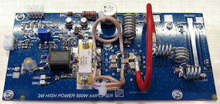
It turns out that there aren't that many options in the 400W category but, as ever, Google is your friend. My Google-Fu directed me to a company that is not well known in the amateur radio world but which must, surely, have at least one radio amateur on its staff, as they produce a really rather nice 550W "gain block".

The Enigma Broadcast PA144-500 takes about 3W of RF, adds 50V at about 15A, together with a large dollop of "dark art" engineering and turns it all into 500W RF output. 

Each amplifier comes with a test report detailing gain, efficiency, harmonic content, etc. backed up with spectrum analyser screen captures of the individual unit under test. The company also provides generic 2-tone test data obtained during the module's development. The numbers are quite impressive, auguring well for a nice clean (and loud) signal from G3WGV!

Of course this is only part of the overall amplifier. To this must be added a substantial power supply, cooling systems, Tx/Rx changeover relays and control circuitry/processing. And a case to put it all in, of course. 


In the beginning

After some 30 years away from 2m and above, I decided that it was time to see what had changed. One thing that had definitely changed was the radio equipment and I was soon kitted out with an Icom 9700, something of a step-up from the Microwave Modules transverter I used to have. A dual band 11 ele (2m)/28 ele (70cm) Yagi fed with EcoFlex 15 coaxial cable completed the set-up.

I soon realised that IO84 is a long way from the activity and that the 9700's 100W really doesn't cut it these days, so my thoughts turned to more power. It quickly became apparent that 2m amps in the 400W-ish class are a) very expensive and b) there are not many suppliers out there and those that are have ludicrously lengthy waiting lists. My thoughts turned to homebrewing.

Really, I am not much of an RF engineer. Certainly when it comes to fast wiggles at 100MHz and above, design seems to be even more of a dark art form that it is lower down the spectrum. So my mind turned to amplifier "bricks" that would limit my design work to the surrounding infrastructure, control circuitry, etc. where I feel much more at home.

I've acquired a suitable amplifier module, so I'm ready to get started!