2022-03-25

Mk II PCB part 2

Yesterday I fired off the Mk II PCB Gerber files into production and I should have the PCBs within a week.

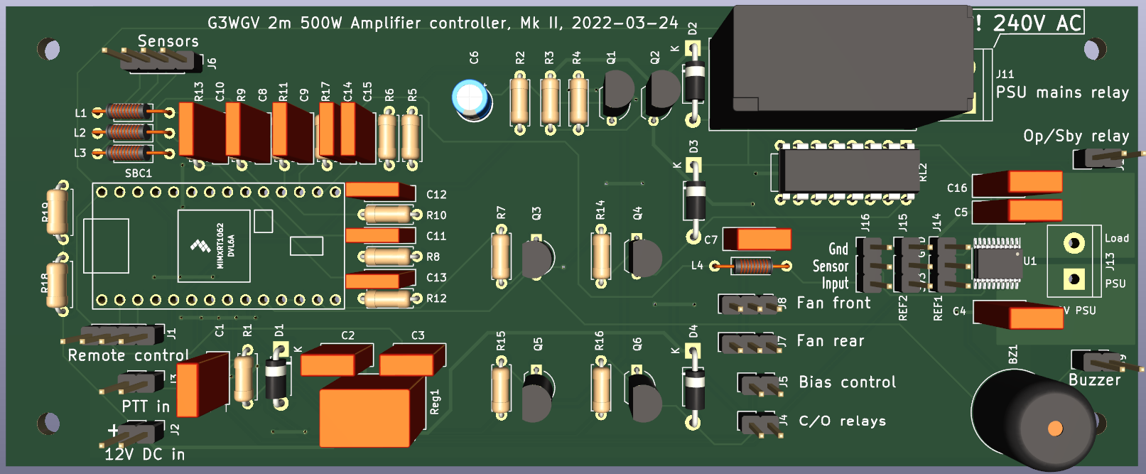
The Mk II PCB in production, with INA253 current sensor
 

One of the many things that delayed proceedings was concern about the introduction of surface mount devices (SMDs). I've never done anything with SMDs and my eyesight ain't as good as it was, so I was somewhat hesitant. In the end I decided that just as it is possible to teach old dogs new tricks so it should be possible to teach myself how to work with SMDs.

I bought an electronic microscope that projects a magnified image of the PCB onto my large PC screen and obtained a hot air gun, solder paste and tweezers. Importantly I also got an SMD practice board and I spent some time yesterday soldering teensy weensy capacitors, resistors and even ICs to it. The first attempts were rather pathetic but I quickly got the hang of how much solder paste to use (very little) and where to put it (at the end of the component solder pads). I think I am now good to go with soldering the INA253 current sensor, which is the only SMD on this PCB.

Coincidentally I have another PCB project on the go (a baud rate converter and radio modem for my weather station) and for that I have gone the whole hog on SMDs. It looks like a trend is developing here. I suspect, in time, that designing and building SMD boards will be as natural as the through-the-hole technology that I have been using for the last 50 years.

I shall report back in due course.

2022-02-16

Mk II PCB

I've been working my way up to a Mk II PCB for a few weeks now and I think it's getting close to time to press the Go! button. There are three principal drivers:

  1. The decision to use an INA253 current sensor instead of the Hall effect device that the Mk I used.
  2. To make improvements to the RF immunity, now that I know that RF just gets everywhere!
  3. To fix various errors in the Mk I design.

The most experimental aspect of this new PCB is the use of an INA253 current sensor. This is a surface mount device and it's the first time I have designed a PCB using SMDs, so that should be interesting. I have discussed this already a few posts back but the fact is that I won't know whether it's a good idea and, importantly, that RF isn't getting into it, until I can test the Mk II board. Fingers crossed!

I've added quite a lot of decoupling to try to keep RF out of places it has no business being. The new PCB design aims to keep this decoupling as close to the SBC input pins as possible, again to frustrate illicit RF ingress. We know that RF is a black art, especially at 150MHz, so again, only testing will reveal the success of otherwise of this strategy.

And, of course, there are the inevitable design errors to fix. As careful as I might be, the Mk I PCB for all my projects always seems to have a few.

The proposed Mk II circuit diagram

The proposed Mk II PCB


Power calibration

Another issue that I've been contemplating for a while is power meter calibration. The amplifier module has forward and reverse VSWR outputs that can potentially provide power and SWR indications but as always with these things it ain't that simple. There are two principal issues to resolve:

  1. The non-linear relationship between sensor output and RF power, as seen in the chart below;
  2. The electrically short length of the SWR bridge, resulting in apparently higher SWR indications than  are the case in practice.

Forward sensor pin value vs.RF power
The non-linearity is difficult to resolve mathematically (at least for my brain that last worried about such things over 50 years ago) so I decided to implement a simple lookup table instead. 

Twenty arbitrary data points define forward sensor pin values and corresponding RF output power. These can be user defined and the results are stored in EEPROM. Power calculations are done by linear interpolation between the nearest two data points.

The table from which this graph derives is based on empirical measurements at the power points marked by vertical drop lines. The graph was then smoothed by eye to produce best guestimate table values. 

I still need to get access to an accurate power meter to validate these values, especially as I would like to implement an overall amplifier efficiency algorithm. That will only make sense if the input values are accurate.

The high SWR indication is interesting. Using my antenna as a dummy load (!) my SWR bridge says that the SWR is 1.2:1. In my software I convert forward and reverse sensor outputs to equivalent RF power and then calculate the SWR using the power SWR formula (1 + sqrt(Wr / Wf)) / (1 - sqrt(Wr / Wf)), where Wf=forward watts and Wr=reverse watts. This results in a reading of around 1.6:1.

It seems that the electrically rather short SWR bridge is prone to a certain amount of leakage and as the reverse power is relatively low, this effect is noticeable as an apparent increase in SWR. 

I am still considering a fix for this but my thinking is that as my sensor pin vs RF power table has removed the non-linearity of the actual sensors then it is a simple matter of scaling the reverse sensor power value to match measured SWR to actual SWR. That is the next thing on my software development task list.
 

2022-01-29

Current affairs

One of the problems that I really want to improve upon is PA current measurement. Reliably measuring up to 20A digitally in what is an electrically rather noisy environment has proved to be problematic, with a mix of common mode rejection issues and RF ingress.

I tried providing a separate 5V power line for the ACS712 current sensor and that did make an improvement, presumably tackling the common mode rejection problem. Still not really good enough though. Next I tried taking the mathematical mean of a series of measurements to try to smooth out noise on the sensor output. Rather surprisingly this didn't help noticeably at all. 

More research turned up a new device, the Texas Instruments INA253, which uses differential amplifiers rather than a hall effect device. This did make a noticeable improvement but the thing that really made the biggest difference was putting a choke/capacitor to ground RF filter very close to the microcomputer input pin. Obviously RF was still getting in there.

The TI INA253 also confers another significant advantage on the design. The differential amplifiers mean that it is possible to reference 0A to anything, including ground. That removes the need to determine the half-Vcc point, something that was a real pain with the ACS712.

First attempt at Mk II PCB circuit

So my current thinking is that I will use the INA253 and that pushes me firmly towards a new PCB, as the INA253 is a surface mount device. There are quite a few other changes that I've made by cutting tracks but there is no way I can do that to bring an SMD into the existing PCB.

Whilst I am at it I will also introduce a potential divider circuit into the temperature sensor input line because the 3.3V maximum input to the microcomputer limits the temperature range to 60°C.

I've made a first stab at the new circuit diagram and will do the PCB layout once I am as sure as I can be that it's correct and as good as I can make it for this iteration. This is normal - the first PCB shows up all the design faults and the second attempt is much better. Occasionally it takes three attempts!

2022-01-15

Improvements...

Well I did say that my projects are never really finished...

Paraphrasing Field Marshal Helmuth von Moltke's famous saying "No plan of operations reaches with any certainty beyond the first encounter with the enemy's main force", I have long since learned that however cunning the design, on the air experience will soon reveal its weaknesses. And so it is with the amplifier. 

Metering

The first problem is metering in general and 50V current monitoring in particular. The readings jump around like a kangaroo even when nothing much is going on (e.g. a steady carrier). Partly this was down to how I displayed the current - there really is little point displaying the load to two decimal places when it is 18 amps! So now, once the current is above 2A the resolution is reduced to 0.1A and above 5A it is further reduced to 1A. That helped.

The real problem though is the measurement methodology. I am using an ACS712 Hall effect device and that produces a voltage output that changes proportionally by 100mV per amp. That's easy enough to measure with the analogue input on the processor but the real problem is jitter on the 5V power supply to the device. A small amount of noise directly translates to changed readings, so, say 50mV of noise on the 5V line is equivalent to 0.25A of jitter. 

5V supply noise
I hooked up the 'scope and sure enough there is some jitter as loads come and go. There's also a lot of general crud on the 5V line as the 'scope image shows. I was rather surprised by how noisy the supply line was but I suppose the fact is that we're not generally too bothered about <100mV ripple on a 5V supply.

5V supply with decoupling
Next I tried putting 470nF + 10uF decoupling capacitors right by the ACS712 and that improved things slightly but it only really removed the high frequency spikes, see image. Most of the noise appears to be coming from the Arduino processor and it seems to be more or less impossible to filter it all out.

I think the solution to this problem is to provide the ACS712 with its own stabilised 5V power source. This is cheap and easy to try out with a low noise precision regulator device such as an MCP1702. I have some on order and will report back in due course.

Bias (again)

I know that I said I wasn't going to bother switching the bias. U turns seem to be quite the rage these days and if it's good enough for our politicians then it's good enough for me. And I think my reasons are better than theirs too.

Whilst I was messing around with the metering problem I decided I should accurately measure the amplifier's quiescent current consumption, which are 33mA unbiased and 225mA with the bias on. I had noticed that the heatsink temperature increased slightly when the amp was on but not transmitting. Well 225mA at 50V is 11.25W and that is not an insignificant amount.

So I decided to connect up the bias control line and write the few lines of code to bring the bias on when TX is requested by the radio and hold it on for five seconds on return to RX. The radio already inserts a 25ms delay before producing RF to give the changeover relays time to change state, so my thinking is that this will be sufficient time for the bias to stabilise as well.

It seems to work OK but I need to do some proper on the air tests to be sure.

There will be more to follow, no doubt.

2022-01-10

Hardware finished?

I think the hardware is more or less finished now but my projects are seldom ever completely finished, especially when it comes to software. Here's some pictures of the finished article


There are still various "improvements" to make but most of these are in the software and it's tricky to take pictures of software...

  • Removal of the tacho monitoring software - I can't find a way to keep RF out of the fans, which are, after all, right up against the "hot" parts of the amp. This is no great loss - I had vague plans of monitoring fan speed to create a control feedback loop but that is provided perfectly well by monitoring the heatsink temperature and setting fan speed accordingly.
  • Consolidation of fan speed control to a single output for both front and rear fans. In the end I couldn't think of any situation where I would want to control them separately, so the code can be simplified. If I do produce Mk II controller PCB it too can be simplified somewhat with the removal of a couple of transistors and associated passive components.
  • Removal of bias control. In fact I never wrote any code for this as in the end I couldn't see any situation when I would want to have the amp powered up (50V supply on) but not biased. There would be a small reduction in power consumption on receive if the bias was turned off but then there is the question of stabilisation of the bias at the same instant as RF is being applied. I don't feel the need to go there.
  • Calibration of the power meter. This really needs me to gain access to a calibrated RF power meter somehow because I have nothing that can measure 400W at 144MHz. If needs be I will rent one some time. It's not really too important, as I have an approximate indication, probably within 10% derived by measuring input power and multiplying by device gain. The 50V power input current provides a useful cross check and seems to be consistent.
  • General ongoing software improvements as I get more experience with actually using the amp - probably a never-ending project!

I fixed the problem of RF getting into temperature sensor logic by cutting a track on the PCB and inserting a 100uH choke with 10nF to ground. Good as gold now. Not worth commissioning a new PCB for that!

So I think I have a usable amplifier. It runs reasonably quiet and cool and local reports are that it is clean, so I shall install it as part of the station once I can find a space for it!

Updates to this Blog will likely be rather less frequent from now on, though I will try to remember to provide occasional updates as the software changes or other improvements come along.

I hope you have found the Blog interesting and comments are always welcome. 

2022-01-06

Something's happening

 Yes! We have progress. 

I finally finished the garage workbench upgrade and very splendid it is too. With the nice new heavy duty vice and bench drill installed, it was time to drill large holes for the fans and finish off the mechanical engineering side of the project. This was, more or less, completed just before the new year and since then I have been testing the amplifier in its almost finished state.

I quickly discovered that the sensors are a problem. RF gets into the wiring and gives silly readings, especially on SSB where the RF output level is continuously changing. The temperature sensor is especially prone to difficulties and I spent some time trying to analyse what was going on. 

Eventually, after much faffing around, I attached the oscilloscope to the temperature sense line and found much RF on the line and, oddly, a fairly significant level shift, suggesting that the RF was getting rectified along the way. This is problematic, as the fans are supposed to be speed controlled by temperature and, of course, that really wasn't working. Worse, because the RF interference made the processor think that the temperature had gone down, the fan logic was working the wrong way round!

Well it turned out that it was my wiring. I had naively assumed that the very well filtered temperature sensor output from the amplifier module together with the high level of screening in the case would mean I could get away with unshielded wires. Nope.

Replacing the sensor connections with shielded wire made a big difference but the temperature display was still slightly unstable. So I decided to go the whole hog and instal a filter comprising a 100uH series inductance and 10nF capacitance to ground at the PCB. That fixed it!

With hindsight, I should have put the input filtering on the PCB at the outset but I was too trusting of the amplifier module filtering and simply didn't think the RF could get around my carefully designed screening quite so easily. As I've said before, I'm not very good at RF engineering, especially the fast wiggles of VHF and beyond.

So I've had a bit of a redesign of the control circuit, putting choke/capacitor filters on all input lines, as shown in the circuit fragment to the left. It won't be possible to modify the existing PCB to accommodate these changes and I also have a couple of  other issues that I commented on earlier, so I reckon I am heading for a Mk II PCB. It's so inexpensive to get PCBs made these days that it's hardly worth doing otherwise.

I'm working on the new PCB layout and will probably get it into production in the next week or so. 

Meanwhile the amplifier has been getting some use in the UKAC contests, which seem to be the only time that there is any actual activity on 2m.